
How Important is Product Data Quality in CAD Modeling?
Table of contents
- What Requirements Are We Talking About?
- What Happens If Requirements Aren’t Met During Design?
- What Can We Do to Maintain Downstream Application Requirements?
- Are Check Lists Really the Best Option?
- How Can CAD Quality Checkers Help?
- Where Are CAD Quality Checker Used Most Often?
- Does My Company Need A CAD Quality Checker?
- Make Data Quality Visible to All with PLM Integration
- In Our Experience…
A Computer-Aided Design (CAD) model usually runs through different phases. From a concept to a released design on which everyone agrees its sum characteristics make it fit for purpose.
These characteristics are not only determined by the shape and geometry of the model but likewise their features of structural and thermal strength, used raw materials, weight, producibility and many more.
However, to tick all the boxes before manufacturing a product, CAD data goes through various steps and iterations, and is used as input for many other systems. Whether in-house, at suppliers, or with customers.
Between the different steps there is potential for time savings that is often underestimated.

CAD data is usually shared within an organization and the different engineering disciplines from design over structural checking, tool design and Numerical Control (NC) coding or tool making.
Often, a Product Lifecycle Management (PLM) system will be used as well, to enable access for each team member in the company. All disciplines and software applications have certain requirements set for the used data. Whether those are documented or not.
What Requirements Are We Talking About?
CAD system requirements are comparatively minor – anyone could design a simple CAD model, right?
Yes, and here is the challenge. When using CAD, we don’t necessarily have in mind what comes after. Or who is going to work on the same model. Within the CAD system there are obvious things – like the measurements of the model – we must put on the design or 2D drawing, but there are also the not-so-obvious ones.
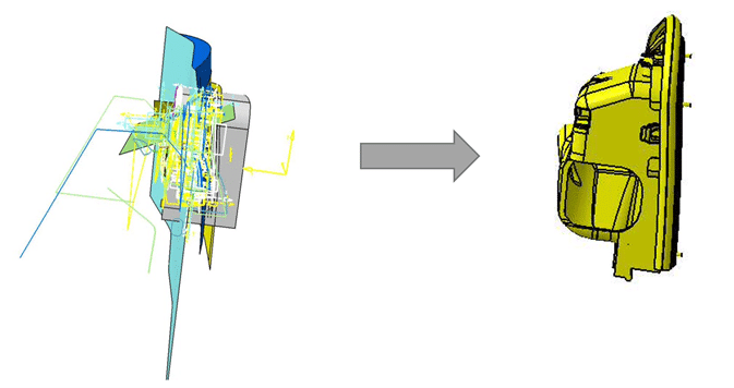
When saving your model to a shared space like a fileserver or your PLM system, you need to ensure that the model has a name that follows a certain standard – at least if you want others to find it. Complex models should be structured in a way that others can easily understand. Here is an example:
Another simple example is that the underlying sketches of a design are constrained to avoid unintentional changes. However, you may not know the various requirements of processes like stress analysis, data conversion, NC coding or even the 3D publishing software your marketing is using to produce content for your website.
What Happens If Requirements Aren’t Met During Design?
In short – a lot of work for us. Prepare for a ringing phone and plenty emails asking how people can find your stuff; for you to hide help geometry; or put material information in; for you to use standard bore holes, or to explain what the model does, even re-doing bits that contain other issues.
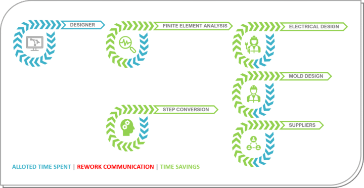
If the initial designer is not fixing the issues, it must be dealt with later in the process – like below.

All that may not sound like a big deal, but it is for an organization employing a lot of people spending time like that. Particularly when a faulty NC code is causing production to halt, or when a customer is chasing the issue.
What Can We Do to Maintain Downstream Application Requirements?
You’ll be making long or, maybe, not so long check lists – it depends. A good thing would be, to just let the designer know all the downstream requirements from the start.
However, before you can do that, you have to let people talk to each other.
The idea is to collect all requirements downstream processes set for CAD data. Like naming conventions for the PLM system and things you want to follow when using CAD. Like hiding help geometry rather than using layers to make things easy for others. Using specific assembly templates you defined, or only using features from a catalogue for standard parts, holes, threads, and fillets that can be manufactured by your machines.
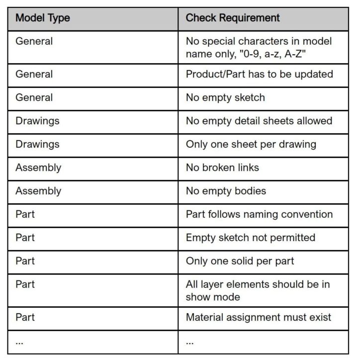
Finally, put all that in a spreadsheet, aka “the check list.” Here is a short example of such a check list (a very short one):
Assuming you follow all those things from your check list your process now looks like this:
Are Check Lists Really the Best Option?
Check lists work. But they’re not an ideal time-saving solution. You do your work, then someone has to go over the check list. Only, you may realize that you forgot a simple thing in the beginning. So, rework starts again.
Let’s assume you only look at the check list once during design. And once more when you’re done with the model. This may lead to an uncomfortable situation where you’re not only having to fix the underlying issue, but all the stuff that’s been done based on the feature that is causing the trouble.
Wouldn’t it be nice to know earlier that you’re on the wrong path? Of course, the solution is not to look through your check list after every single click in your CAD system.
How Can CAD Quality Checkers Help?
Luckily, large organizations realized that these issues cause more than extra design and reworking time. They extend the time to market and cost even more money. So, software manufacturers have been asked to deal with the issue.
For most CAD systems today, check tools are available – so what is a CAD Quality Checker and how does it work?
It’s a good idea to have a list of things to keep in mind when working with CAD models. But you wouldn’t want to go through that list manually.
Instead, transform your unique check lists into a set of instructions for your check tool software which is usually running directly in your CAD environment – so you’ll get a button in your CAD system that runs the checks for you. Good news!
Such tools offer the possibility to check your work against your company requirements or the requirements of a supplier or a customer. Like with a spell checker, you do some work then you run the check, understand that you are on the right path or apply a fix and move on. This style of working eliminates that you can detect errors very late in the process.

Above you can see how that may look like in CATIA V5 when running Q-Checker
After running the tool, you’re presented with a list of all your checks and under each check that revealed an issue (the yellow, blue and red dots), you get a list of your model features that aren’t meeting your standard.
In the example above, we found an issue in “Dimension 1” that we can either fix and do a re-check or directly “heal” by pressing the red cross. That’s nice because some of the things will actually be “repaired” for us automatically.
If you run the tool every now and then you can ensure that you’re in line with your company standards across your entire CAD design process. And you’ll save time looking through lists, taking phone calls, replying to emails and running through extensive rework.
Where Are CAD Quality Checker Used Most Often?
Many large Automotive and Aerospace OEMs have been asking their suppliers to use check tools for decades already.
Suppliers checking against their customers’ requirements are saving time for their customers but not necessarily for themselves. That is a must for those suppliers, but they may leave a huge time saving potential open when not applying a similar strategy to their own development work.
Luckily, most check tools are not only supporting one list of checks but offer the possibility to choose against which standard you want to check your design. So, just like that, you can work in line with your own process requirements or those of customer A, B, C and so on.
Does My Company Need A CAD Quality Checker?
Well, there’s no “catch-all” answer. So, it’s likely you’ll have to break out the calculator.
Think of the percentage of time used for communication and re-work in your CAD environment. How many people are working in CAD? How many people outside of CAD are blocked by potential errors. And for how long?
Calculate the potential time saving and see if this justifies the procurement cost. And especially do that if you are already using such a tool for your customer anyway.
Make Data Quality Visible to All with PLM Integration
Designers get instant feedback when using CAD quality checking software. But, they’re the only ones who know whether the model still contains errors, or not.
In some cases – for example, when working in large teams – it’s beneficial to know whether the model is ready for downstream usage. In PLM systems you usually have different maturity levels for your models.
So, let’s assume that one stage is named, “release”. And from that maturity level, everyone knows that the designer is ready with their work, and it’s okay to re-use the model in other applications. At this stage, the model should not contain any errors. It should be ready for whatever comes next.
In such a scenario, it would be good to know whether the model is clean, before you pass it to the “release” stage in your system. You may even make its quality status a prerequisite to enter that stage and then automate that in the system.
In reality, of course, we’re always working on a model in parallel with others. So it may not be a good idea to wait until the very end (release) to have everything nice and clean.
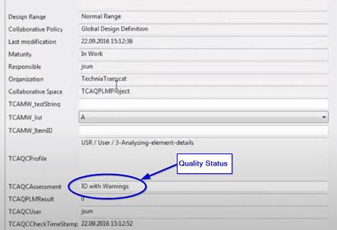
You’ll also want to have the models clean so others can collaborate on the design or use it in their FEA system. For that, we could add a new attribute to your PLM object that tells us the quality check status of your model. This attribute can then be updated each time you store the model to the system. So, everyone searching for your model would be presented with its quality status straight away.
Now that you have the status in the database, you can also automatically check it and make it a mandatory input for the maturity change.
Below you can see what happens in PLM during maturity change, depending on the model’s quality assessment:
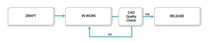
Like we said before, we’re always working in parallel. So it doesn’t make much sense to have only one quality gate at the very end of the process. Instead, define which minimum mandatory quality level a model should have before it can enter a certain maturity level.
In the example below “in order” models may enter any gate. Whereas “deficient” models only pass the prototype state, and so on.

Here’s one way this process can appear in 3DEXPERIENCE:
In Our Experience…
It’s always worth doing the calculation and figuring out if your organization can benefit from CAD quality checking software. We’ve seen the value first hand at organizations where teams are working together on CAD designs, and at companies with long downstream processes.
Most of all, designers and their colleagues appreciate the creases ironed out of their design processes. This simple solution could be the quick fix for better team collaboration and a faster time to market that you’ve been looking for.
Discover how your business can save time, and provide supplier confidence by improving Product Data Quality at the TECHNIA Software PLM Innovation Forum!

